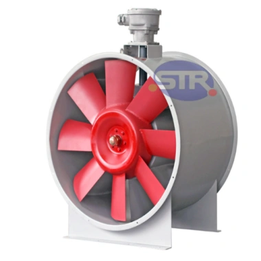
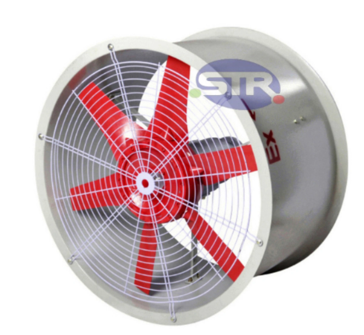
Explosion-Proof Axial Flow Fan BT35

GB/T3836.1、GB/T3836.2、GB/T3836.31、IEC60079-0、IEC 60079-1、IEC 60079-31

Default airflow direction of the fan: front of the impeller
| Explosion-Proof Marking | Protection Rating | Rated Frequency (S) | Cable Outer Diameter | Inlet Thread |
|---|---|---|---|---|
| Ex db IIC T4 Gb Ex tb IIIC T135°C Db |
IP54 | 50 | φ10-φ14 | G3/4" or pressure plate |
| Model and Specifications | Impeller Diameter (mm) | Rated Voltage (V) | Rated Speed (r/min) | Impeller Angle | Airflow (m³/h) | Total Pressure (Pa) | Installed Power (kW) |
|---|---|---|---|---|---|---|---|
| BT35-2# | 200 | 380/220V | 2800 | 43° | 1230 | 112 | 0.09 |
| 1450 | 618 | 64 | 0.06 | ||||
| BT35-2.8# | 280 | 2800 | 35° | 2921 | 190 | 0.25 | |
| 1450 | 1510 | 105 | 0.18 | ||||
| BT35-3.15# | 315 | 2800 | 3074 | 218 | 0.37 | ||
| 1450 | 1998 | 141 | 0.25 | ||||
| BT35-3.55# | 355 | 2800 | 3367 | 246 | 0.37 | ||
| 1450 | 2188 | 160 | 0.25 | ||||
| BT35-4# | 400 | 3560 | 260 | 0.37 | |||
| BT35-4.5# | 450 | 38° | 3450 | 142 | |||
| 42° | 4644 | 150 | 0.55 | ||||
| BT35-5# | 550 | 380 | 38° | 7655 | 116 | ||
| 43° | 8316 | 123 | 0.75 | ||||
| BT35-5.6# | 560 | 9581 | 173 | ||||
| 48° | 11682 | 186 | 1.1 | ||||
| BT35-6.3# | 630 | 41° | 10736 | 154 | |||
| 45.2° | 14454 | 160 | 1.5 | ||||
| BT35-7.1# | 710 | 40° | 13400 | 178 | 1.1 | ||
| 43.5° | 16160 | 189 | 1.5 | ||||
| 960 | 46° | 14498 | 123 | 1.1 | |||
| BT35-8# | 800 | 44° | 31325 | 180 | 2.2 | ||
| 37073 | 248 | 4.0 | |||||
| BT35-9# | 900 | 46° | 35227 | 200 | 3.0 | ||
| 39800 | 230 | 4.0 | |||||
| BT35-10# | 1000 | 48300 | 247 | 5.5 | |||
| 54300 | 268 | 7.5 | |||||
| BT35-11.2# | 1120 | 42° | 56460 | 353 | |||
| 46° | 67892 | 415 | 11 |
1. This series of ventilators is designed based on the three-dimensional flow theory of impellers, with meticulously engineered test data to ensure excellent aerodynamic performance. They feature low noise, high efficiency, minimal vibration, and low energy consumption.
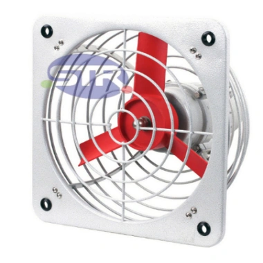
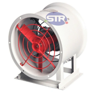
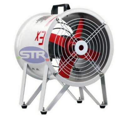
2. The ventilator comprises an explosion-proof motor, impeller, air duct, and protective cover.
3. Suitable for ventilation and exhaust applications; can also be installed in series within short exhaust ducts to increase duct pressure.
4. Cable wiring is standard. For steel pipe wiring, specify this requirement when placing an order.


| Machine Number | L (mm) | D1 (mm) | D2 (mm) |
|---|---|---|---|
| 2# | 280 | 210 | 260 |
| 2.8# | 290 | 340 | |
| 3.15# | 325 | 375 | |
| 3.55# | 320 | 365 | 415 |
| 4# | 370 | 410 | 460 |
| 4.5# | 460 | 510 | |
| 5# | 510 | 550 | |
| 5.6# | 450 | 570 | 620 |
| 6.3# | 640 | 690 | |
| 7.1# | 720 | 770 | |
| 8# | 630 | 810 | 860 |
| 9# | 910 | 960 | |
| 10# | 1010 | 1060 | |
| 11.2# | 1130 | 1180 |
1. Suitable for Zone 1 and Zone 2 locations in explosive gas environments;
2. Suitable for Class IIA, IIB, and IIC explosive gas environments;
3. Suitable for Zone 21 and Zone 22 locations in explosive dust environments;
4. Suitable for Class IIIA, IIIB, and IIC explosive dust environments;
5. Suitable for temperature classes T1 to T4;
6. Widely used in hazardous environments such as refining, chemical processing, textiles, and military industries, as well as offshore oil platforms and oil tankers;
7. Indoor and outdoor use.